Kicks - Static Electricity
During the 2013 Betfair World Snooker Championships the match
between Graham Dott and Shaun Murphy was interrupted due to Graham
Dott having suffered several sever static electic shocks.
The Match officials overcame the
problem by damping the carpet with water from a hand spray, which
seem to have the desired effect.
Perhaps some research instigated by
Norman Clare, into the possibility that static electricity could be
the cause of 'KICKS' may have reduced or even removed the problem
especially the comments on clothing, shoes and the carpet.
For some reason Norman Clare never
published the research but his son Peter, prompted by the Dott
situation, thought it was time that the work was available.
The experiments and research was
carried out in 1987 in the Billiard Room of the long established
'Gentleman's Club called the Lyceum (now sadly no longer in
existence), when it was situated in Paradise Street. Norman was a
member and in fact was President of the Club on two occasions and
so was able to have permission to use one of the four Ashcroft
Billiard tables that were in the Billiard Room.
The report follows :-
STUDY REPORT
E. A. CLARE & SON Ltd.
STATIC ELECTRICITY AND THE "KICK"
PHENOMENON
JULY 1987
PREPARED
BY :-
COMPUTING IN
BUSINESS
SUITE 40,
WIRRAL BUSINESS
CENTRE
GORSEY LANE
BIRKENHEAD, L41
1JW
REF NO.
BTAS 31899
CONTENTS
1. INTRODUCTION TO
REPORT
1.1 Terms of reference
1.2 Confidentiality
2. INTRODUCTION TO STATIC
ELECTRICITY
3. COMPANY PROFILE
4. MATERIALS ANALYSIS
5. FIELD EXPERIMENTS
5.1 Introduction to the "KICK"
effect
5.2 Experimental work
5.3 Analysis of field ant motion
effects
6. CONCLUSIONS AND
RECOMMENDATIONS
Appendix A References
Appendix B Basic programs used in
evaluation of analyses.
©
1987-2013 -E.A. Clare & Son Ltd.
1.
INDUCTION TO
REPORT
1.1 Terms of
Reference
Computing In Business has been
retained by E.A. Clare & Son Ltd T/A Peradon (and Fletcher
Ltd.), manufactures of billiard/snooker cues and accessories, to
investigate and report upon the nature and values of static "build
up" on billiard and snooker tables taking cognizance of
environmental surrounding. The prime objective of the study is to
evaluate whether or not the measured levels of static would be of
significant magnitude to produce the phenomenon known as
"kick".
The study has attracted financial
support under the department of Trade and Industry's Business and
Technical Advisory (BTAS) scheme (project reference No. 31899).
Computing in Business is obliged to include in the report the
following DTI terms and conditions applicable to projects
undertaken under the BTAS scheme.
"Whilst every care has been
taken to ensure that the advice in this report is correct, neither
the Secretary of State for Trade and Industry, the Secretary of
State for Defence nor Salford University Business Services Ltd.
Will accept responsibility for loss, damage, etc., howsoever
arising, occasioned by the implementation of such advice. No
liability should rest upon the Secretary of State for Trade and
Industry, the Secritary of State for Defence, nor upon Salford
University Business Services Ltd. If implementation of any of the
advice contained in this report would involve use of patents and
like protection not held by your Company. In such circumstances
appropriate legal advice should be sought.
It is a condition of payment by the
Department of Trade and Industry for work done in connection with
this project that a copy of the report on the project shall be
supplied in confidence to the Department of Trade and Industry.
If, as a result of the advice and
recommendations contained in this report, you are proposing to
purchase any paint or equipment, you are strongly advised, before
entering into any commitment, to contact your regional office of
the Department of Trade and Industry in order to ascertain the
up-to-date position regarding government grant to which your
company may be entitled."
1.2 Confidentiality
The information contained in this
report, along with such information as may be provided during
discussions with parties other than Peradon is to be regarded
as strictly confidential & can only be used with the permission
of E.A. Clare & Son Ltd.
2. INTRODUCTION TO STATIC
ELECTRICITY
2.1 General
Though one of nature's most widely
displayed phenomena, static electricity is among the most
capricious. Many of its manifestations are familiar to all of us,
in the form of lighting and its aftermath thunder. It was the
Greeks who first noticed electrostatic energy when they rubbed
amber against cats fur and an electrostatic charge resulted. They
names this effect tribos charge which results from bringing
together of two different materials and then separating them.
Static charged have caused little or
no serious problems to industry in the past. However, in the last
ten years modern society has rapidly come to depend on electronic
devices. These devices are based increasingly on low-power logic
silicon chips which are extremely susceptible to electro-static
discharges. Moreover, at present even more sensitive technologies
are being developed, typically silicon-on-sapphire (S O S) and
Gallium Arsenide (GaAs).
Static discharge can damage
devices at five basic stages:
1) within the
semiconductor manufacturer's plant;
2) at the distributor's
site;
3) within the company which is
using the devices to build a product;
4) in normal operation at the
end user's site;
5) during service and
repair.
In a typical office environment
static electricity can be generated in many ways; the most common
causes are frictional contact and movement between the following
surfaces and/or items which may be found in many offices:-
1) work surfaces which are
waxed, painted, varnished, or consist of natural plastic or
laminate.
2) Floors of sealed concrete,
waxed or varnished wood, vinyl tiles and all carpets containing
natural or man-made fibres, especially nylon.(It would be
interesting to know what the carpet at the Betfair 2013 World
Snooker Championships was made of)
3) Chairs/clothes; where
operators wearing clothing made of man-made fibres move to and fro
on an insulated chair.
4) All types of common
articles left on desk tops, including expanded polystyrene,
envelopes, plastic bags, trays, plastic folders, binders and coffee
cups.
In general the level of static
produced increases considerably as the surrounding air becomes
drier, which is reflected in a fall in relative humidity. However,
the situation is complicated by the relationship between humidity
and temperature; colder air holds water vapour less well then warm
air, and consequently low temperatures imply low humidity and
greater static problems. (Under TV lights the atmosphere is
drued out so the humidity is low)
Typically in the summer, when the
relative humidity is between 60% - 80%, walking across a nylon
carpet will generate approximately 1,500 Volts. However, in winter,
when the relative humidity has fallen to between 10%-25%, the same
movement will generate voltages in excess of 30,000 Volts. At
standard office temperatures of 20-25 degrees centigrade, it may
safely be said that static problems will certainly occur if the
humidity, for whatever reason, remains consistently below 40%.
Typical voltages causing shocks to
operating staff are in the order of 3,000 Volts or more. These
voltages are also sufficient to cause data loss on a computer
system.
It should be noted that when
computer systems are subjected to static discharge the screen will
normally go blank, the system will reset itself, and data currently
being worked upon will be either lost or corrupted. These symptoms
are often attributed to mains interference, spikes, or other such
factors. However, the most likely cause is electrostatic
discharge.
Certain types of carpets, chairs and
other office equipment are referred to as having "anti-static"
properties, meaning that under normal conditions movement on or
around them will not create static electricity. However, such
equipment and carpeting is extremely susceptible to dust and dirt
impregnation which reduces its anti-static effectiveness and has
the further disadvantage of offering no common earth path for
discharge.
The maximum protection from unwanted
static can be gained only from conductive materials which can be
earthed in a safe manner.
The human Body As A
Capacitor
Capacitance measurements for the
human body range from 80 pfd (pico Farads) to 500 pFd at the
farthest extreme.
Women usually have higher
capacitance than men due to the thinner soles on their shoes.
Thus, walking across a floor or
carpet will charge up a human's capacitance. Charging currents lie
between hundreds of pico amps and a few micro amps and total charge
ranges from 0.1 to 5 micro coulombs.
Calculating the voltage V = Q/C for
a 150 pFd person charged with 3 micro coulombs produce a sum of
20,000 volts.
Raising an arm changes the stored
voltage by 100v. Standing up changes the stored voltage by 1000 to
1500v. Grounding oneself momentarily, then lifting one foot off the
floor will increase the stored voltage by 1500 to 2000v.
In an extreme case a person can
charge up to 40,000 volts. Above this figure a corona discharge
effect self-limits the voltage to this figure.
3. COMPANY
PROFILE
Peradon is a market leader in
the UK for the manufacture of billiard/snooker cues and tips.
From a Liverpool site it
manufactures cue tips from selected leather for the UK and export
markets and carries a wide selection of snooker and billiards
accessories which are factored.
An associate company within the
group, E.A. Clare and Son (Trading as Thurston, Peradon &
Drakes Pride) are leaders in the field of snooker and billiard
table manufacture.
For many years there has been a
problem with the phenomenon known as the "kick" which causes the
cue ball and object ball to display different characteristics from
normal in certain instances of impact.
The phenomenon is infrequent and
erratic but due to the high current level of commercialisation of
the game, it is now assuming significant importance in top level
tournaments.
Very little study has previously
been undertaken in this area and the company could benefit greatly
from new products and/or services should a solution to this
phenomenon be found.
4. MATERIALS
ANALYSIS
As previously described in the
"Introduction to Static Electricity" the surface conductivity of
materials plays an important part in the generation and dissipation
of static electricity. The following table gives a general
indication of the electrical properties of materials and their
conductances.
MEASURED SURFACE RESISTIVITY OF
SNOOKER TABLE COMPONENTS ACCESSORIES.
|
Material
|
Surface Resistivity
|
|
|
|
|
Slate Bed
|
10 10
Megohms
|
|
Table Cloth
|
10 14
Megohms
|
|
Wood Surround
|
10 8
Megohms
|
|
Rubber Cushion
|
10 15
Megohms
|
|
Chalk
|
10 12
Megohms
|
|
Snooker Balls
|
10 11
to 10 13
Megohms
|
|
Cue Shaft
|
10 8
Megohms
|
|
Cue Tip
|
10 11
Megohms
|
All readings were taken at 65%
RH and 19.4 0C.
From the above readings it can
be seen that the materials used in the manufacture of snooker
tables have surface resistivities in the range 10 10 to
10 15
ohms per square; the exception being the snooker cues which
have surface resistivity of approximately 500 megohms for both Ash
and Maple types, with the Ebony and base measuring 10,000
megohms.
The readings obtained indicate that
surface resistivity levels of this magnitude will not afford fast
dissipation of any static charges generated as indicated in Section
(5). Typically decay rates were measured at 34 to 137 seconds for a
charged ball on baize.
The surface resistivity of the ash
and maple cues measured at 500 Megohms will allow a transfer of
charge from the person holding the cue to the ball.
5. Field
Experiments
5.1 Introduction
Please note that bibliographic
references (*) in this section of the report are detailed in
Appendix A.
Evidence exists that the "kick", an
unexpectedly dull impact between cue ball and object ball causing
both balls to move unpredictably in both direction and velocity,
can be caused by an interposing substance or layer at the point of
impact of cue and object balls (1). To date, the most accepted
postulate has been the presence of cue chalk on this impact point;
a previous experiment has seemingly confirmed this effect by
deliberately placing layers of paper or fine cloth at the impact
point and observing motion similar to that seen when the "kick"
occurs. (2). There is, however, much anecdotal or circumstantial
evidence to suggest that cue chalk is by no means the sole cause of
"kick" behaviour. For example, it is noted that some players are
particularly susceptible to the "kick"; as are certain tables, or
types of cue, or sets of balls, and even climatic variations have
seemed to play a part (2). While mathematical analysis of the
motion and collisions of snooker and billiard tables have been
carried out (4) (5), the prevalence of the "kick" effect has not
been of sufficient volume or repetition to warrant any analysis of
its effects.
If the deduction is made from the
previous research that the "kick" is due to a sudden frictional
force at the point of impact (similar to the force caused by a
layer of paper or chalk at the impact point), it may be postulated
that the reduction in rotational velocity is due to the effects of
local charge on both balls and table, especially in the case of a
slow shot. The following summaries of experimental work and
analysis of the dynamics of ball motion will explore this
hypothesis.
5.2 Experimental
Work
The experimental conditions were
those much favoured by many scientific researches during relaxation
- a standard snooker table, cue, and balls, in carpeted
environment. Relative humidity was measured at 59.7% and
temperatures at 19 degrees centigrade. Measurements of electric
field were carried out using a field-mill type of meter, connected
to an x-y plotter when dynamic effects were being observed.
Resistivities were measured using an electronic meter capable of
resolving 100,000 Megohms.
5.2.1 Resistivities
As is normal, the cues consisted of
an ebony base and a wooden shaft. The resistance of both types of
cue wood made available, Ash and Maple, was approximately 500
Megohms, and that of the ebony base was of the order of 10,000
Megohms. The table surface resistivity was greater than 30,000
Megohms. A check on the resistance across the diameter of the balls
showed that the black was noticeably more resistive (30,000
Megohms) than the other balls, which all showed approximately
10,000 - 20,000 Megohms. However, the presence of moist air on the
surface of any ball could reduce its measured resistance to 500
Megohms.
5.2.2 Initial experiments and
the electrostatic effects of different ball colours
To determine the approximate size of
field effects seen in snooker play, a single ball was struck around
the table to return to the player after 5-6 collisions with side
cushions, and the field meter used to detect the presence of
electrostatic charge, if any, on the ball. This confirmed the
presence of static charge on the balls; although a residual of up
to 700 V/m could be occasionally detected before the shot. The
field close to the ball surface after the shot was below 5 KV/m
only in one case, and occasionally much higher. At this point, as
can be seen from the results tabulated below, it was noticed that
certain colours could repeatably produce hight charge effects than
others.
-
|
Colour
|
Field at ball surface (KV/m)
|
|
White
|
-0.7
|
|
Red
|
-7
|
|
Yellow
|
-11
|
|
Green
|
-5
|
|
Brown
|
-5
|
|
Blue
|
-12
|
|
Pink
|
-6
|
|
Black
|
-12
|
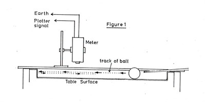
A more precise variant of this
experiment was conducted, using the system shown in figure 1,
overleaf. Each colour was used several times; the subsequent table
records average values of maximum measured field during each pass
of the ball below the sensor. In some cases, a large variation was
recorded, and this is expressed in the table.
|
Colour
|
Max. field 2cm above
ball
forward
return
|
|
White
|
-1.4
-0.7
|
|
Red
|
-1.5
-1.7
|
|
Yellow
|
-1.0
-1.3 to -2.2
|
|
Green
|
-1.1
-1.5 to -3.0
|
|
Brown
|
-1.2
-1.0 to -2.2
|
|
Blue
|
-1.5
- 2.7
|
|
Pink
|
-1.6
-1.5
|
|
Black
|
-1 to
-2
-1.5 to -5
|
Thus, the colour effect was
confirmed, and it was found that a cushion bounce could increase
ball charge by up to 200%. This latter effect was, however, not
readily repeatable, and a large variation existed between the
occasional hight values of 500% for this increase and the more
usual 30% - 50% changes. It was noted that the largest variations
in this experiment occurred with the brown ball, where on one
occasion a reading of -14 KV/m was obtained.
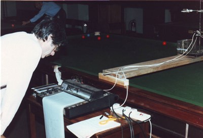
picture of actual set up for the
experiments
5.2.3 The effect of the type of
shot
The same apparatus as in 2.2 was
then used to investigate the effect of fast shots, slow shots,
screw-back, with the black ball as cue ball. From the results shown
in the table below, it can be seen that the type of shot has an
effect in most cases and that the strength of shot also is a factor
in the size of charge produced on the ball.
|
Type of shot
|
Field produced
|
|
Screwback
|
-4 to -6
|
|
Side
|
-1 to -2.6
|
|
Screw
|
-1.5 to -1.6
|
|
Slow screw
|
-2 to -3
|
|
Top
|
-0.7 to -1
|
|
Stun (shortrange)
|
-0.4 to -0.6
|
|
Stun (long range)
|
-0.9 to -1.2
|
5.2.4 Table Charge
By paying a ball past the sensor of
the field meter, the effect of charge left on the baize was noted
as being of opposite polarity to the charge on the ball, and of
between 10% and 30% of the magnitude of ball electric field. This
charged "track" extended by approximately a centimetre around the
line of ball movement.
In addition to this local charge
density it was noted that an overall charge density on, and close
to, the table could be generated from the presence and movement of
players around it.
5.2.5 Decay of
charge
Decay times of all the above
phenomena were noted. While initial decay of ball charge was of the
order of 10% per second, this rapidly settled to an overall decay
time of 30 -15 seconds to discharge.
5.3 Mathematical analysis of the
changed caused by the presence of electrostatic charge on
cueball and object
ball.
5.3.1 Velocity changes due to
electric field effects between charged cue ball and object
ball
The assumptions in the following
analysis are as follows:-
(a) - the cue ball is hit in such a
way as to induce perfect rolling motion with no trace of skid.
(b) - an electric charge is picked
up by the cue ball on impact of the cue, and no charge is lost or
gained during cue ball travel.
(c) - the charge on the ball behaves
as a point charge.
The condition (a) is one which can
be readily achieved by a slow shot, as shown by previous researches
(5), and can even be created on a fast shot if the cue impact point
is correctly chosen. Condition (b) is probably an
over-simplification, but serves to underline the fact that in
practice, some extra charge may be created by friction between
table and cue ball or between side cushion and cue ball. Condition
© is almost certainly an over-simplification, but probably valid at
separations of cue ball and object ball of greater than a few
millimetres.
To find the size of the charge held
by the cue ball if the voltage of its surface us known, the
standard formula is used:-
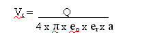
where: a = distance between point
charge and measured voltage
Q = size of point
charge
Vc = measured potential
at distance a from point charge
eo = free space
permittivity
er = relative
permittivity of cue ball
Simple transposition gives :-
Q = Vc
x 4 x
π x
eox
erxa
from experimental data, the
approximate voltage given to the cue ball is 100v, the ball radius
being 3cm., and the assumption may be inserted that the relative
permittivity of the polymeric resin of the ball is 4. This gives,
when these figures are inserted into the above formula a charge of
1.3 x 10 -9 coulombs on the
cue ball; a figure not unreasonable given that a human (of
approximate 1000 pf capacitance to earth) with a 100v potential may
store 10 -7 coulombs
(6).
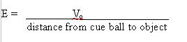
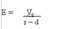
If the voltage of the object
ball is Vo , the size of the
field produced by the object ball (assuming it is a point charge)
is, from another standard equation:-
Thus, if the initial ball separation
is s, and the distance travelled is d, this may be formalised
slightly:-
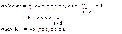
At any point in the cue ball travel,
the force exerted by the field on the charged ball is
F = Q x E
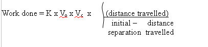
Thus, the energy loss corresponding
to work done against the field by bringing the balls closer
together is, at any instant in the ball motion,
Work done = Force x distance moved
by the force
= Q x E x d
Inserting the previous formulae
:-
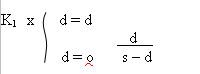
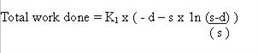
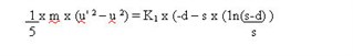
Therefore, the total work done
between the initial cue ball position and the current position d is
found by the integration, over the distance d,
where the quantities K,
Vo, and
Vc,
which do not vary with distance, have been combined into
K1.
The integral is standard readily found in mathematical
reference books (3), and has the value :-
[s - d - s x 1n(s-d)]
Once the limiting values are
inserted, some algebraic manipulation gives
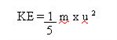
To enable comparisons with the
original kinetic energy of the cue ball, the kinetic energy of a
rotating sphere assuming no skid component is, form the standard
formula :-
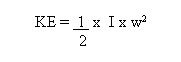
Where I = moment of inertia of a
rotating sphere
w = rotational velocity
The moment of inertia of a sphere,
I, is another standard formula,
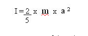
Where m = mass of the sphere
a = radius of the sphere
The angular velocity is obtained
by
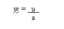
where u = linear velocity of the
edge of the ball
a = radius of the ball
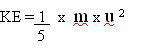
Substitution of the definitions
given for the moment of inertia and the angular velocity gives
:-
Thus, if the energy change due to
work done by the electrical effects is expressed as a change in
ball velocity, to the value u' , the above equations may be
combined as :-
Further algebraic manipulation gives
the result that the fractional velocity change u'/u, is given
by
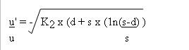
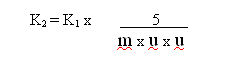
Where all constant terms have been
combined into K :-
5.3.2 Discussion of velocity
change effects
It must, at this point, be noted
that the asymptotic behaviour indicated by the logarithmic term is
unrealistic, since it indicates the fairly elementary fact id
electrical theory that two charges of the same polarity would need
an infinite amount of work to overcome their repulsion and
superimpose. Thus, the first numeric substitutions into this
equation concerned the effect of reductions in the size of the
final separation used as one of the limits of integration.
Using ball voltages of 500 volts,
initial separation of 30cm. , and an initial cue ball velocity of
10cm/second, the following data resulted from numeric substitution
into the program shown in Appendix b :-
|
Final d value
|
% change in velocity
|
|
27 cm.
|
0.3
|
|
29 cm.
|
0.6
|
|
29.9 cm.
|
1.2
|
|
29.99 cm.
|
1.7
|
|
29.999 cm.
|
2.3
|
|
29.9999 cm.
|
3.4
|
Since the close
contact effects of like charges on snooker balls are not easily
predicted, but are unlikely to occur at separations greater than
1cm, the 29 cm. mark is used as the standard integration limit in
the following numeric investigations. It must be noted, however,
that the size of velocity loss may be up to five times larger than
this limit shows.
The effect changes in the initial
cue ball velocity is shown below, using an initial separation of
30cm. and 500V on each ball :-
|
Initial velocity
|
% change in velocity
|
|
10cm/sec.
|
0.6
|
|
5cm/sec.
|
2.4
|
|
2cm/sec.
|
14.2
|
Clearly, slower shots are highly
vulnerable to electrostatic effects.
5.3.3 Effects of velocity
change on object ball trajectory
The error angle caused by the
changes in one component of linear velocity may be estimated by the
following method, using the diagram in Figure 2. if, as an example,
a quarter - ball shot is undertaken at the separation between cue
and object balls of 30 cm., the angle between line AA (joining both
ball centres) and the desired direction of the cue ball can be
calculated by :-
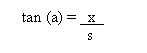
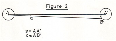
Where x is the distance between the
aim point for a straight shot and that for a quarter - ball shot. A
good estimate for x is half the ball radius; inserting numeric
values, the angle a is therefore, in this case, 2.86 degrees.
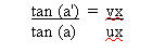
The linear velocity of the ball has
two components with respect to AA' ; ux, along AA' which is
attenuated by electrical field repulsion to a value vx, and uy,
normal to it, which is not deflected. If the final angle of
approach is a', the rekation between a and a' can be expressed as
:-
A decrease of 10% of the component
parallel to AA' gives the value 0.9 to the right side of the above
equation. This gives a' as 2.57 degrees, and the error angle as the
difference between a and a' is 0.28 degrees.
The diagram in Figure (3) is a
simplified version of that used by a previous researcher (4) into
dynamics of collision between billiard balls, who also supplies a
formula for the calculation of the angular error of the object ball
at the target position ;-
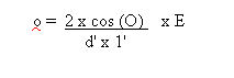
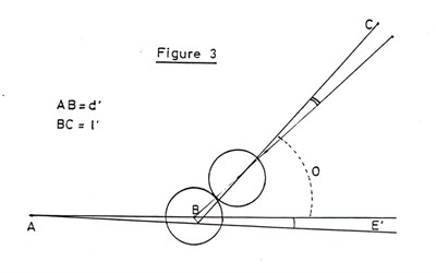
Where O = angle between error- free
cue ball direction and object ball direction
E = error angle, between
desired and actual cue ball direction
d' = distance from cue ball to
object ball
1' = distance from object ball
to target position
For the case of quarter - ball shot,
the angle O is approximately 45 degrees. The product of d' and 1'
is maximised when these are equal; 1' is therefore set at 30 cm.
These numeric values, if substituted into the above equation, give
a value of 4.4 degrees to 0. the linear error is simply 0 x 1' if 0
is expressed in radians; for the shot under discussion, this gives
an error of 2.3 cm.
It is, therefore, clear that if the
electric field causes a velocity change of 10%, an error of greater
than a ball radius is induced in a fairly short quarter - ball
shot. This is, however, seldom fatal to the desired effect of a
snooker shot even at top levels of play. It is interesting to note
that the effect is similar in size to that produced by the "nap" of
the table bed cloth, and may in some situations be mistaken for
it.
5.3.4 Effects of the last
quarter - turn of the cue ball before impact
The previous sections considered the
cue and object balls as point charges, however, experimental
evidence tends to indicate that when a ball is rubbed on the table
surface, the charge on the ball is localised to the region of
contact between ball and table. This implies that any charge given
to the ball from the cue is similarly localised. Thus, motion of
the charge is not linear, but consists of a rotational pattern, and
although the integrations over cue ball travel distance in the
previous work would become more complex, it is expected that
displacements above and below the line of motion of the cue ball
centre would be cancelled by the integration. This cancellation
effect is expected to break down at close distances between cue
ball and object ball, and the following analysis therefore explores
the effect of point charges on the surfaces of the balls on
rotational velocity.
The simplified situation shown
in Figure 4 is assumed. Initial separation s of the charges at B
and E can readily be found, by using the right-angled triangle BCE.
The distance CE is the linear travel corresponding to rotation of
the last quarter - turn, i.e. a + πa/2 where a
is the ball radius. The distance BC is equal to the ball radius
a.
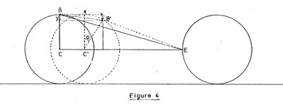
When the ball has moved to a new
position centred on C', the new positio of the charge is b' ,
having moved by the amounts marked as x and y on the diagram. This
is due to the linear translation CC' and the angular movement
o.
From the diagram, it is clear that
the distance y can be expressed as :-
y = a x (1 - sin (o)
)
The expression for x is ;-
x = CC' + (a x coz (o) )
CC' is equal to the distance moved
by the arc contained by the angle o, and if o is expressed in
radians the above expression becomes :-
x = a x (o + cos (o) )
Thus, both positional variables have
been expressed in terms of the angle of rotation o.
It is now assumed that the identity
below is valid:-
Total work done = work done against
+ work
done
against
field x
component
y component
and, from the previous section,
where the constant K is given
the value which sets the charge on the cue ball to 10
-9 coulombs, as was the case in the
previous analysis. This is done by transposition of;
Q = K x
V
if V is taken as 500 Volys, K
has the approximate value of 2 x 10
-12.
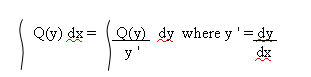
Thus, each component may be
evaluated in turn, using the following method of integration over
one variable with respect to another :-
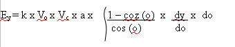
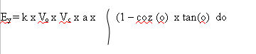
In the case of y component, the main
equation for integration, after some algebraic manipulation,
consists of;-
From the definition of the
relationship between y and o given earlier, the differential term
is readily extracted, and the above equation becomes
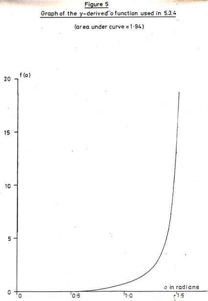
This is simplest evaluated
numerically from the area under the curve of the function being
integrated, and the limits are chosen to be the start point (o=0)
and the value of o at which 1mm separation occurs (o=1.52 radians).
Figure 5 shows the function plotted between these limits; numeric
substitution using the above equation, voltages of 500V, and the
value of the area under the plotted curve gives;-
Ey = 3 x 10
-8 joules
From the earlier analysis, the
initial kinetic energy of ball motion can be found from
and, if the ball has 0.1 Kg
mass and is moving at 5 cm/second, the value of KE is 2 x 10
-5. The loss in velocity
v/vo can be found
from:-
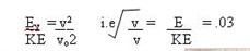
Therefore, approximately 3% of
velocity loss is predicted in the last quarter turn. However, if
the voltages are doubled, the loss in velocity is similarly
doubled; 1KV on both balls could account for 6% loss in spin
velocity.
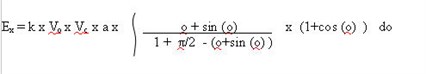
A similar procedure carried out for
the x component gives the initial equation:-
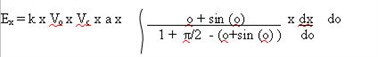
The differential can be
readily determined from the previous relation between y and o. and
thus ;-
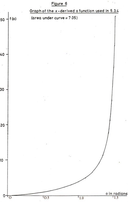
Numeric evaluation of E
for voltage values of 500V, in a manner exactly parallel to that of
the y component (the function to be integrated is shown in Figure
6) gives the total energy loss as 2 x 10⁻⁷
, and therefore the loss in velocity of this component
is evaluated from;-
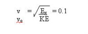
Thus, 500V on each ball gives a 10%
loss in spin velocity of the component perpendicular to the main
ball rotation. It is interesting to note that if voltage is
increased by an order of magnitude, a not impossible situation,
this analysis suggests a complete stop of the "side" rotation of
the cue ball.
5.3.5 Discussions of effects
of the last quarter - turn
This analysis is purely exploratory,
and is only intended to give an indication, not a total
mathematical description, of the way electrical fields affect ball
motion. However, if the above is even approximately a valid model,
it is clear that a substantial change occurs in rotational velocity
as the balls collide. This is equivalent to an increase in drag or
friction qt the collision, and could certainly account for
different sound made by the "kick"; according to reports, the
impact is much less sharp than that of a normal snooker collision.
Further credence to the hypothesis of drastic loss of spin is given
by previous experiments (1) increasing friction at the impact
point, where a "kick-like" phenomenon occurred.
It must be noted that the change in
rotation need not be a decrease; the analysis is of enough
generality to be equally valid in the case of a negatively-charged
local area passing over a positively - charged spot on the table,
and therefore cause an increase in rotational velocity.
6. CONCLUSIONS AND
RECOMMENDATIONS
6.1 Summary of Electrostatic
Effects and their analysis using a simple model
Because the "kick" is an uncommon
occurrence, it was not expected that the preceding experimental or
theoretical work involving simplified models would indicate its
presence. However, a number of possible mechanisms can be
postulated from the following conclusions, and all are worthy of
further study.
Even in the idealised case of a
perfectly rolling ball, with no skidding motion between cue strike
and impact of cue ball and object ball, the cue ball will lose up
tu 5% of its initial kinetic energy in the process of overcoming
electric field repulsion due to the charges in both cue and object
balls. Thus is derived from the mathematical analysis of a fairly
slow shot in which the initial cue ball velocity is 5cm/second and
the voltage on each ball is of the order of 500 Volts. The latter
is well within experimentally measured values.
The balls and the table baize are
excellent insulators, and the charge is delivered to the cue ball
by the cue tip. Thus, although the overall voltage as measured a
few centimetres from the ball may be in the 100V - 500V range, a
small area of the ball may be at a potential well in excess of 1KV.
While the charge distribution and movement when the balls are close
to impact are difficult to predict, a simplified analysis of the
last quarter turn of the ball before impact indicates the
possibility of loss of 10% of at least one of the two possible
rotational components of ball motion.
6.2 Charge Transfer
Mechanism
The source of the electrical charges
given to balls and table is the players involved. As is well known,
merely working across certain types of carpet will create a
potential; the process of moving an arm may add 100V to this.
Indeed, during experimental work, one participant was found to be
generating in excess of 1KV during the process of walking from one
shot to the next. The two types of cue made available were not
resistive enough to prevent transfer of charge to the cue ball.
Conversely, the wood of the table was conductive enough to
dissipate this change when the players body rested on it in
preparation for a shot. Dissipation of charge through the table
baize is also too slow to significantly affect any charge placed on
the balls in the time scale of the period between shots.
In addition, anecdotal evidence
concerning the increased likelihood of the "kick" happening when
the black ball is the target may be explained by the fact that in
top level play, it is the ball most handled and therefore most
likely to absorb electrical charge from the gloves of the
referee.
6.3 Charge distribution on the
table
The presence of the "track" of
residual charge left by a moving ball (and of opposite polarity to
that on the ball) was noted during experimental work. Although this
charge is an order of magnitude below that of the ball involved, it
is evidence that charge transfer is occurring during ball
travel.
However, if the track is parallel to
the cue ball movement, as often occurs when a player is
successively potting red and black balls into one pocket, little or
no electrical work is done because the charges are not moving
closer together, and the maximum effect expected is a deviation of
the order of millimetres at the object ball position. If the line
of motion of the cue ball and the line of the track of positive
charge cross, the analysis is to a first order similar to that of
the last quarter - turn, and about 10% of velocity loss may
occur.
6.4 Other Effects
It must be emphasised that the
mathematical analyses have, in the interests of simplicity, not
considered the following effects which may contribute towards the
electrical field effects present in the system.
6.5.1 Frictional motion
In the perfectly general case, the
cue ball starts its motion with a period of skidding motion, then
settles into pure rolling motion. While it is possible to play a
shot with no skid component whatsoever, merely by hitting the cue
ball in a certain way, a long-range shot (in which the skidding
motion imparts greater accuracy) may cause the first 30% of cue
ball movement to be entirely frictional before settling into
rotation. Thus, in addition to the charge given to the cue ball by
the player, some further charge may be created triboelectrically by
this frictional motion. This mechanism is corroborated by the
simple experimental test of wiping the ball against a few
centimetres of table baize and thereby producing a voltage of 1KV
on the ball.
6.4.2 Charged range
effects
Since the electric field of the
system of two balls is inversely dependent on their separation, it
becomes theoretically infinite when contact is made. In practice,
the simplistic analysis does not give ludicrously high values of
kinetic energy loss if the integration of thus quantity is limited
to sensibly close final separations of 1mm or 0.1mm. However,
because the predicted asymptotic behaviour is unrealistic, the
close range effects of localised charge on both balls and table
should be examined both experimentally and theoretically.
6.4.3 Charged table
effects
The effects on a charged ball moving
across an oppositely charged track have not been considered. It is
expected that the effect will be similar in nature but of opposite
sign to those produced by the existing analysis of the last
quarter-revolution of the ball. This indicates the possibility of
an increase in angular velocity as opposed to the decrease
predicted in the previous cases. The balance of rotational and skid
velocities mat thereby be upset and a skid component produced at
the expense of rotational velocity, giving both increased
likelihood of frictional generation of charge and of
unpredictability of impact due to velocity changes.
In addition, the effect of
negatively charged spot on the ball passing directly over a
positively charged track left by a previous shot may cause a
drastic apparent increase in friction due to the electrical
attraction of this system.
6.5 Methods of reducing
electrostatic charge effects
Table earthing would accomplish
little of use, since the cloth is the site of the problem and is a
highly effective insulator. The use of anti-static carpets may
alleviate the accumulation of charge by players, but very few
carpets exist which are completely reliable in this respect.
Anti-static spraying or cleaning agents applied to carpets would
possess the disadvantage of periodic treatment, but may provide
effective interim solution.
The application of these widely used
methods of static control would lower, without entirely removing,
the localised charge which this work indicates may be the major
source of unpredictability of ball trajectory.
Since the presence of human players
almost guarantees the generation of static charge, and ideal
measure would be to create a table surface which could easily
dissipate electric charge when the player placed a hand upon it.
The major disadvantage with this approach is the possibility that
the new anti-static surface could have noticeably different playing
characteristics not acceptable to top - class players accustomed to
the electrostatically-vunerable tables already in use.
Because the analysis indicates that
local charge effects may well be of paramount importance in
producing the kick, the dissipation of charge on the ball could be
an effective solution. Since it is probable that the differences
between the ball colours in charge creating and retaining ability
are due to either different concentrations or different
compositions of the dyes used to colour the resin, a search could
be made for dyes with the correct colours, chemical compatibility
with the ball material, and electrical resistance reducing
properties. In the absence of this, a bulk additive could be found
or a surface layer incorporated into the ball to reduce effective
charge retaining ability.
To reduce the effect of the player
on the cue ball, cues of greater resistance could be used, thereby
preventing the main mechanism of charge transfer from operating.
This would not remove the triboelectric effect between balls and
table, nor would it prevent the referee from charging balls removed
from pockets, nor would it prevent the creation of local charge
table areas caused by players hands.
APPENDIX
A
REFERENCES
1 "what causes the
kick", R. Levi, "The Billiard Player", series of articles Oct, 1923
- Jan. 1924
2 as (1)
3 CRC Handbook of
Chemistry and Physics, 56h Edn. , p. A-121
4 "Billiards
Mathematically Treated" , G. W Hemming Q.C. , Macmillan 1899
5 "The Mathematics of
Snooker" , A. G. Mackie, J. Inst. Math. Applic. Vol. 18 p.
82-89
6 see for example "ESD
Protection Test Handbook", Keytek Instrument Corp.
In addition to these specific
documents, all of the mathematical techniques used may be found in
any introductory undergraduate text. This is also true for all of
the electrical physics used.
APPENDIX
B
BASIC programs
used in evaluation of analyses
The following
programs were used on a sharp computer PC-1246. Due to memory
restrictions, little user friendliness has been incorporated.
1. program used to
evaluate velocity loss in 5.3.2
10 M = 0.1
20 A = 0.03
30 R = 8.85 * (10^
-12) : R=R*4
40 INPUT "CUEBALL VOLTS";W
50 INPUT "OBJECTBALL VOLTS";V
60 INPUT "SEPARATION";S
80 INPUT "FINAL DISTANCE";D
90 INPUT "START VELOCITY";U
100 K = 4 * PI * R * A * 5 / (M * U
* U)
110 F = D + (S * LN ( ( S-D/S) )
120 Z = SQR (1- (K * V * W * F)
)
130 Z = 1 - Z
140 PRINT Z
150 END
2. Program used to evaluate x
function used in 5.3.4
200 INPUT O: P = O * 57.3
210 A = O + SIN (P)
220 B = 1 + COS(P)
230 C = 1 + (PI/2); C = C - A
240 D = A * B / C: PRINT D
240 GOTO 200
(n.b - the computer used could not
evaluate trigonometric functions in radians, so the variable P is
simply O converted from radians to degrees)
3. Program used to
evaluate the y function used in 5.3.4
400 INPUT O: O = O * 57.3
410 A = 1 - COZ (O)
420 B = TAN (O)
430 C = A * B: PRINT C
440 GOTO 400
(n.b - O converted to radians for
the reason given above)
© 1987-2013
-E.A. Clare & Son Ltd.
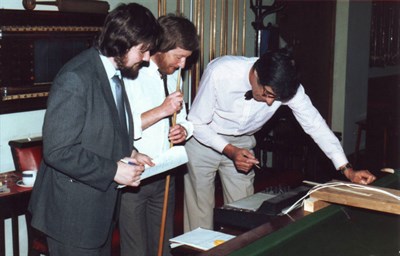
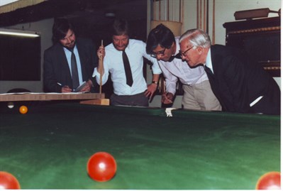
Additional pictures taken
in 1987 during the experiments (all picture copyright
of E.A. Clare & Son Ltd
& Peter Clare):-
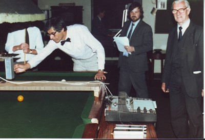
Norman Clare
is on the right of the picture
© 1987-2013
-E.A. Clare & Son Ltd.
This
article and picture is the copyright of E. A. Clare & Son Ltd.
and can not be used as a whole of in part without the permission of
E. A. Clare & Son Ltd. and when permission granted
acknowledgement of the source clearly must be given.
© E.A. Clare & Son Ltd.
2018. © Peter N. Clare 2018
Reproduction of this article allowed only with the permission from
E.A. Clare & Son Ltd.
eshop -
thurston.co.uk
email -
thurston@eaclare.co.uk
phone - +44
(0)151 482 2700